One of the biggest plusses to hand laying turnouts is that you're not constrained by
the sizes and geometries available from the different manufacturers.
You can pretty much do anything you want. I ran across a situation where I had to do
something a little funky to build a passing siding on the mountain division.
When I was building the mainline I deviated from the plan and set the mainline 4 inches closer to the front of the layout to make
it more accessible to an operator.
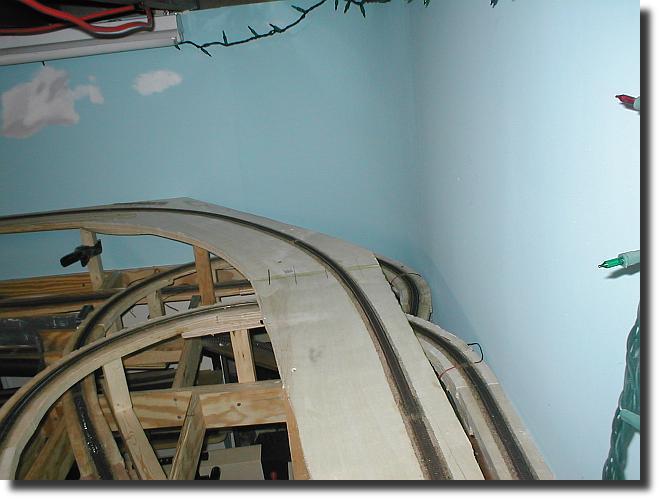
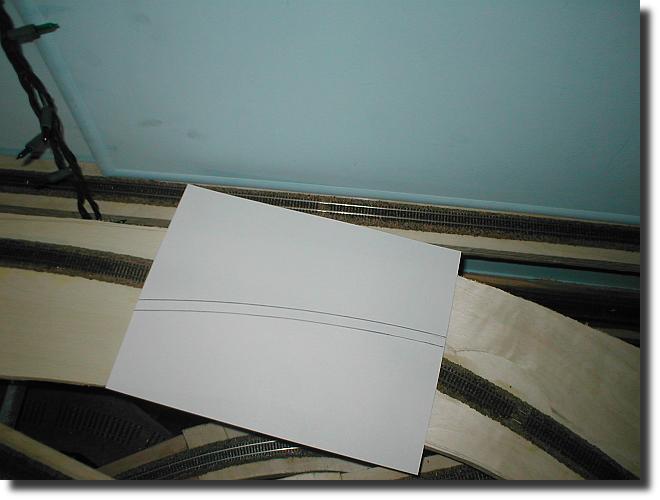
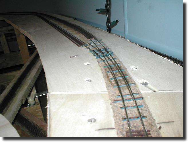
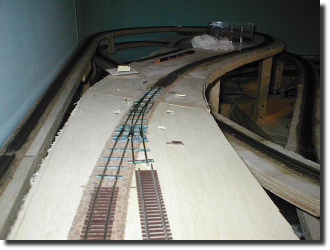
I wanted to put in the passing siding pictured below but realized if I placed the turnout(center bottom in the image) where
I had originally planned the siding would be too short. This meant in order to get the siding length I wanted(6 feet), I would have to build a turnout on the spiral.
Here's how I did it.
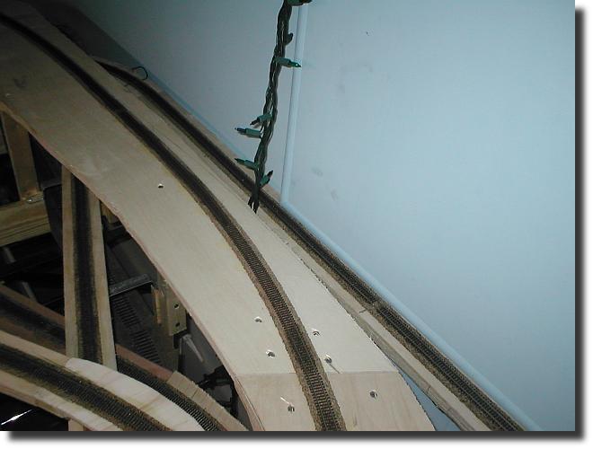
Here are a couple of location shots of the siding.
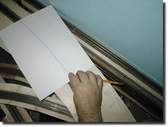
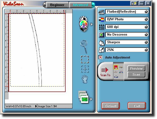
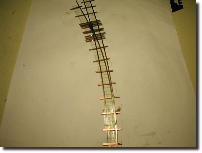
I first took a blank 8.5 X 11 sheet of paper and lay it on the track placing the bottom edge of the paper
parallel with the ties. This would be starting point of the turnout. I then tool a pencil and rubbed the lead over the
top of the rails to trace the spiral.
I took the completed rubbing and scanned it into my computer.
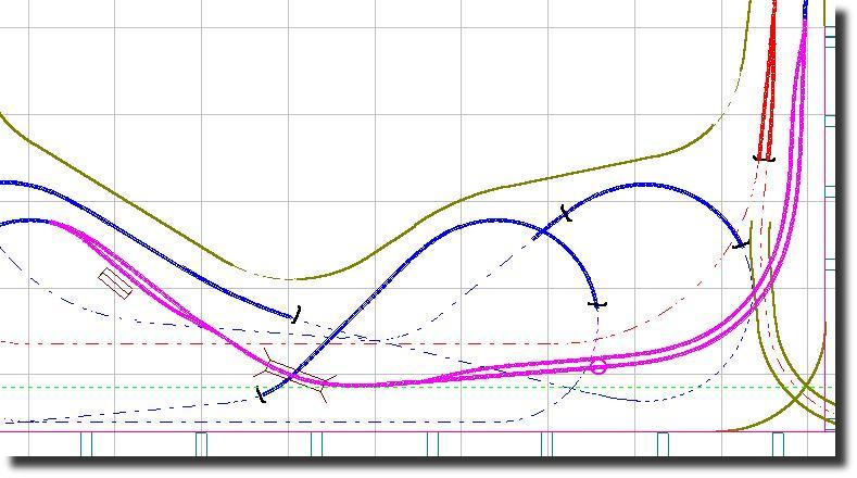
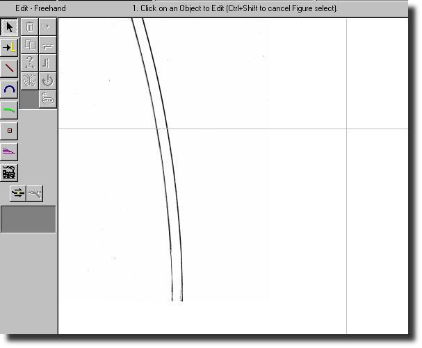
I ended up with a scanned image size of 1221 X 1633. I reduced the image size by a factor of 4 to 305 X 408 using a program called
Ifranview and saved the image as a bitmap. I opened up Cadrail 8 and imported the
bitmap by selecting File--->Import---->Load Picture.
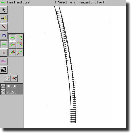
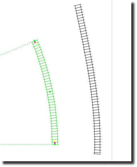
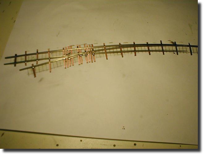
I could now overlay the image with the N scale track style using the freehand spiral tool. I had to play with it a little while before I finally got something to fit.
I then created a section of curved track with the PC to Radius tool and adjusted the radius to 18 inches using the properties tool.
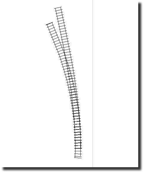
I took the curved section and laid it on top of the spiral. I added a 2 inch section of straight track to the curve to complete the turnout template.
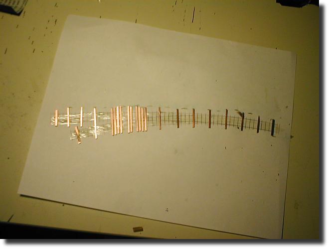
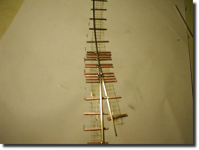
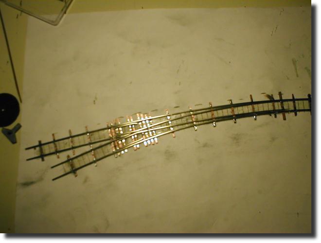
I printed the template and started building the turnout.